How to Configure the Virtual Router Redundancy Protocol (VRRP) on Hirschmann Layer 3 Switches with HiOS-3S & 3A and Firmware Version 07.0.00 or Higher
This article describes the basic steps required to configure the Virtual Router Redundancy Protocol (VRRP ) on Hirschmann Platform V Layer 3 switches running the HiOS firmware version 07.0.00 or higher and the new HTMLv5 Graphical User Interface (GUI).
HiOS-3S or 3A & Firmware 07.0.00
With the introduction of the HiOS firmware version 07.0.00, the switch agent’s Graphical User Interface (GUI) has been changed from a Java based interface to a HTML v5 interface.
Configuration Tasks:
The configuration of the routing function usually contains the following steps:
- Draw a Network Plan
Create a picture of your network so that you can clearly see the division into subnetworks and the related distribution of the IP addresses.
This step is very important. Good planning of the subnetworks with the corresponding network masks makes the router configuration much easier.
2.Router Basic Settings
Along with enabling the global routing function, the router basic settings also contain the assignment of IP addresses and network masks to the router interfaces, and then enabling the routing function on that specific interface.
3. Configure VRRP setting
a. Enable VRRP globally
b. Enable VRRP on the port
c. Create the virtual router ID (VRID)
d. Assign the virtual router IP address
e. Enable the virtual router
f. Assign the VRRP priority
Virtual Router Redundancy Protocol:
VRRP is a type of “gateway redundancy”. VRRP describes a process that groups multiple routers into 1 virtual router. End devices always address the virtual router, and VRRP helps to ensure that a physical router belonging to the virtual router takes over the data transmission. Even if a physical router fails, VRRP helps to ensure that another physical router takes over the distribution tasks as part of the virtual router.
VRRP has a typical failover time of 3 to 4 seconds when a physical router fails.
The routers within a network on which VRRP is active specify among themselves which router is the master. The master router controls the IP and MAC address of the virtual router interface. The devices in the network that have entered this virtual IP address as the default gateway use the master as the default gateway.
If the master fails, then the remaining backup routers use VRRP to specify a new master. The backup router that wins the election process then takes over control of the IP address and MAC address of the virtual router. Thus, the devices find their route through their default gateway, as before. The devices see solely the master router with the virtual MAC and IP addresses, regardless of which physical router is actually behind this virtual address.
VRRP Terms:
Virtual router - A virtual router is a physical router or group of physical routers that act as the default gateway in a network using the Virtual Router Redundancy Protocol.
VRRP router - A VRRP router is a physical router with VRRP enabled. The VRRP router is part of 1 or more virtual routers.
Master router - The master router is the physical router within a virtual domain that is responsible for forwarding data packets and responding to ARP queries. The master router periodically sends messages (advertisements) to the backup routers in the virtual domain to inform them about its existence. The backup routers save the advertisement interval and VRRP priority contained in the master router advertisements to calculate the master down time and skew time.
IP address owner - The IP address owner is the VRRP router whose IP address is identical to the IP address of the virtual router. By definition, it has the VRRP priority of 255 and is thus automatically the master router.
Backup router - The backup router is a VRRP router providing a stand-by route for the master router. The backup router is ready to take over the master role, if the master router fails.
VRRP priority - The VRRP priority is a number from 1 through 255. VRRP uses the priority number to determine the master router. VRRP reserves the priority value 255 for the IP address owner.
VRID - The virtual router ID (VRID) uniquely identifies a virtual router.
Virtual router IP address - The IP address of the virtual router instance.
The Network Design:
In this article, we are using Two MSP30 switches with Layer 3 Advanced features to configure two Physical Router Interfaces on each MSP30.
We have configured interface Port 1/1 and Port 1/2 as the physical router interfaces using IP Address in the two separate subnets.
Router # 1 Router # 2
Port 1/1 192.168.1.120/24 192.168.1.121/24
Port 1/2 172.16.120.252/24 172.16.120.253/24
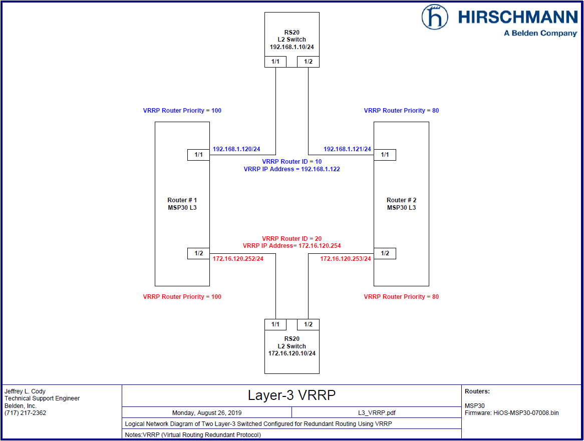
After having the basic routing functions configured and tested on the routers shown above, we will configure Router # 1 to function as the “Master” and Router # 2 to function as the “Backup” VRRP Routers for both the 192.168.1.0/24 and 172.16.12.0/24 networks.
The Configuration Steps:
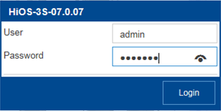
Log into the Router # 1’s GUI with a user ID that has administrative privileges. In the switch’s default configuration, this would be accomplished using the User ID of “ admin “ and a password of “ public “.

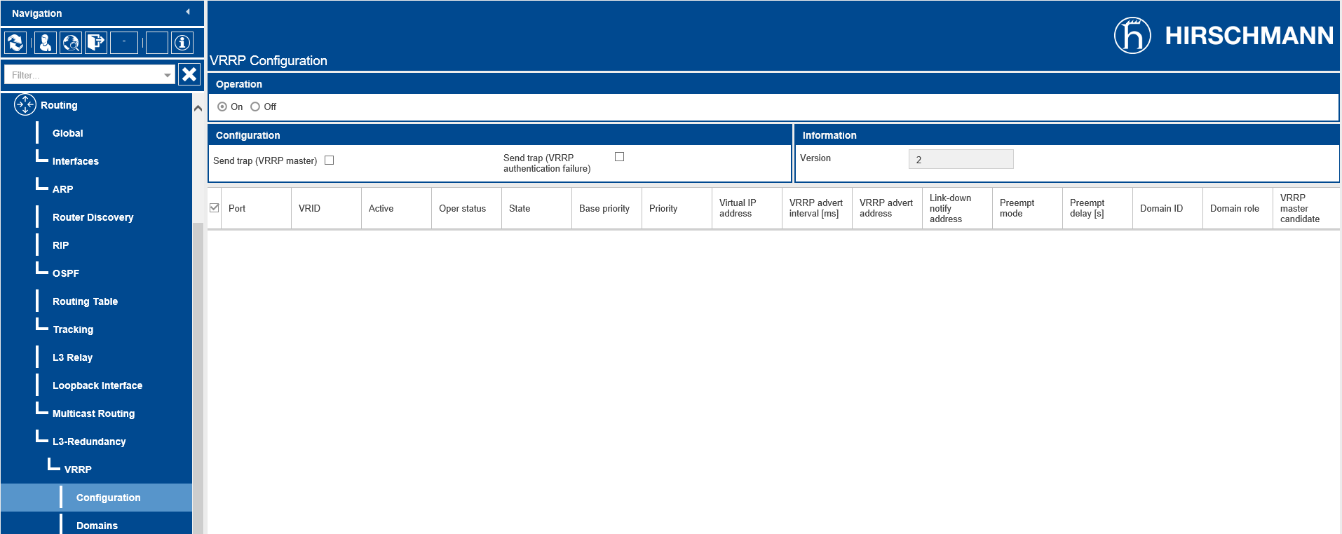
Navigate to the Routing – Layer3-Redundancy-VRRP-Configuration page of the GUI.
Enable the VRRP Configuration operation by selecting the On Operation option radial button and then click the
Write button ( ) at the bottom of the page.
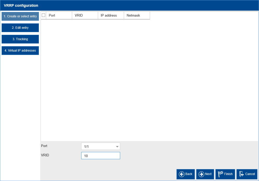
Click the Wizard button ( ) at the bottom of the page.
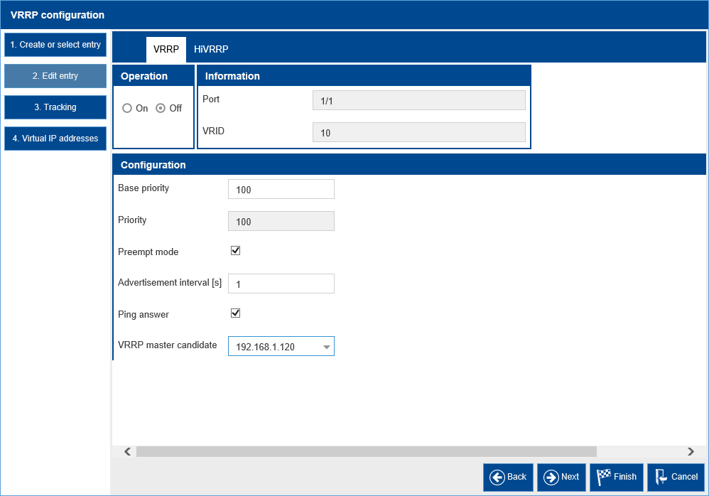
Select Port 1/1 for the Port entry and enter “ 10 “ for the VRID (Virtual Router ID), then click the Next button ( ) at the bottom of the page.

Ensure that the VRRP tab is visible, and then enable the VRRP Operation by selecting the On Operation option radial button.
Drop down the VRRP master candidate box and select “ 192.168.1.120 “ , then click the Next button
( ) at the bottom of the page.
Click the Next button ( ) at the bottom of the page, we will skip over the tracking options since that will be covered in another article and technically is not required for the operation of VRRP.
Enter “ 192.168.1.122 “ in the Virtual IP Address field and then click the ADD button.
Then. Click the Finish button ( ) at the bottom of the page.

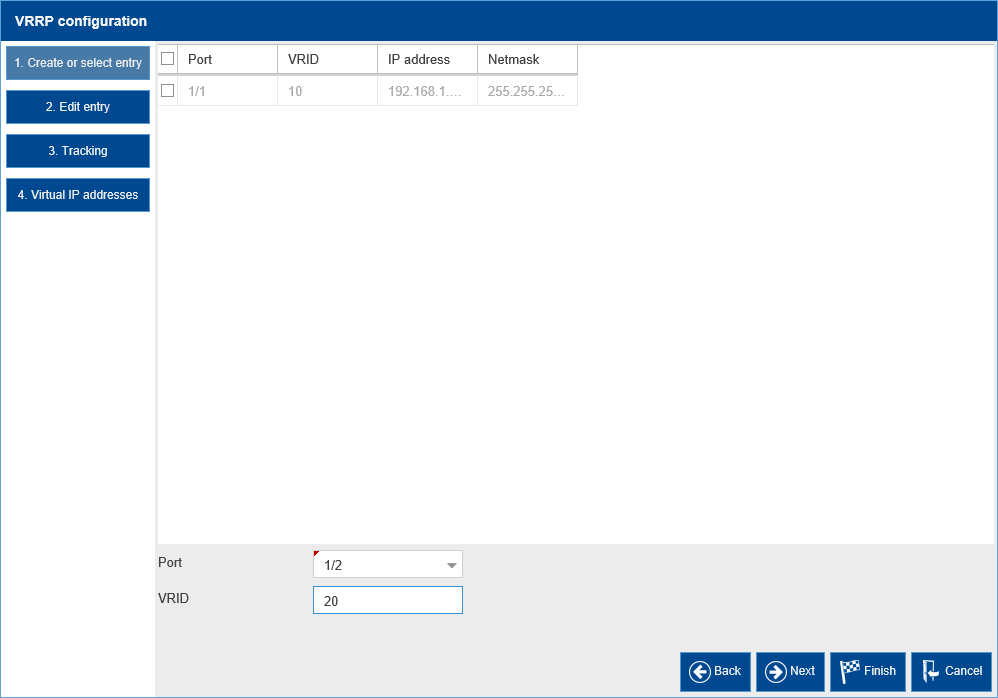
We then repeat the same steps to configure the VRRP configuration for the router interface configured on Port 1/2.
Click the Wizard button ( ) at the bottom of the page.
Select Port 1/2 for the Port entry and enter “ 20 “ for the VRID (Virtual Router ID), then click the Next button ( ) at the bottom of the page.

Ensure that the VRRP tab is visible, and then enable the VRRP Operation by selecting the On Operation option radial button.
Drop down the VRRP master candidate box and select “ 172.16.120.252 “ , then click the Next button
( ) at the bottom of the page.

Click the Next button ( ) at the bottom of the page, we will skip over the tracking options since that will be covered in another article and technically is not required for the operation of VRRP.
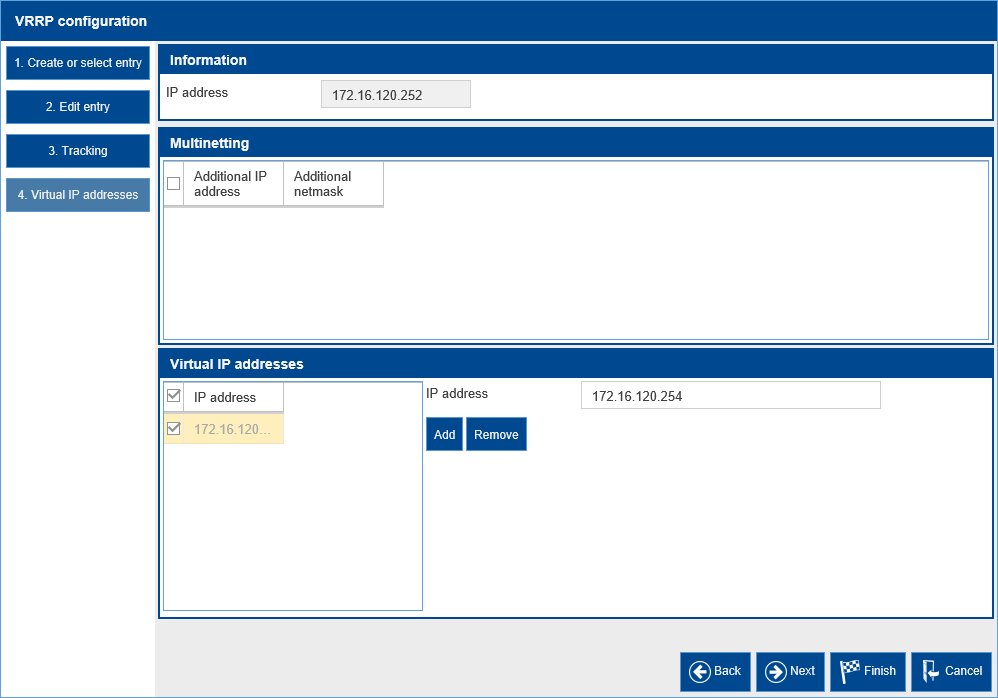
Enter “172.16.120.254 “ in the Virtual IP Address field and then click the ADD button.
Then. Click the Finish button ( ) at the bottom of the page.

Back on the VRRP Configuration page, ensure that both of the entries are Active. If they are not click the Load button ( ). If they still are not Active, then click the Active check boxes for each of the VRRP entries, and then click Write button (
 ) at the bottom of the page.
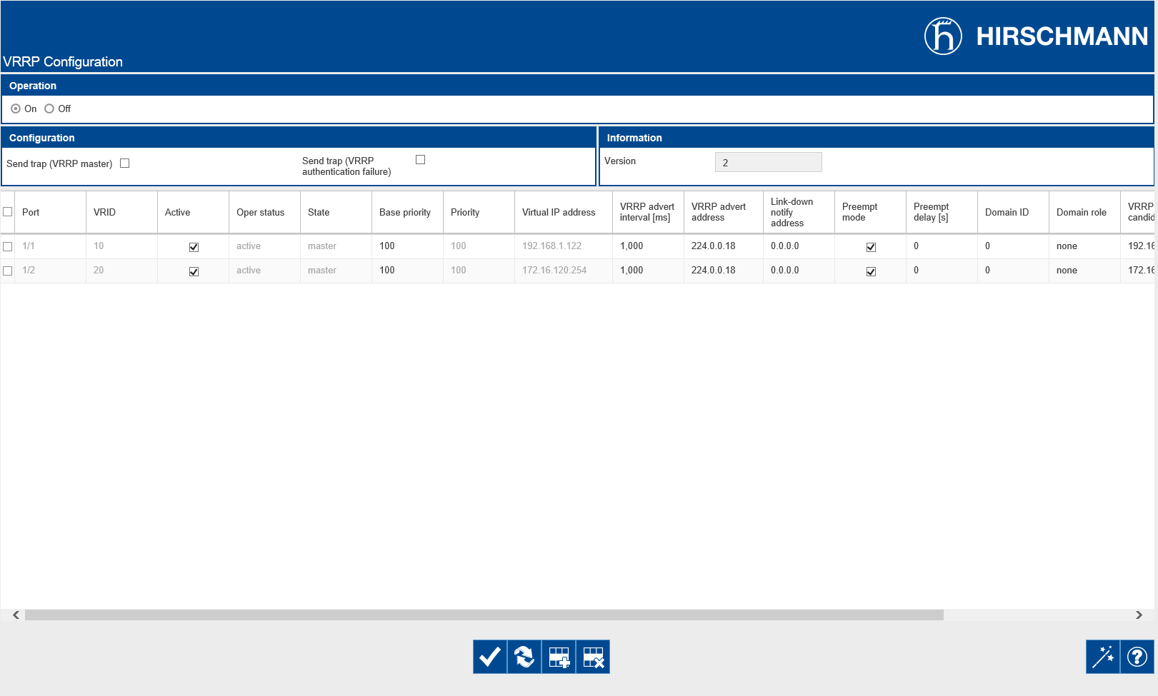
You should now see both of the VRRP instances configured on this router are Active, and the state of each instance is Master. You may need to click the Load button ( ) one final time.
This completes the steps required to configure Router # 1 as the VRRP Master for both the 192.168.1.0/24 and 172.16.120.0/24 networks.
Log into the Router # 2’s GUI with a user ID that has administrative privileges. In the switch’s default configuration, this would be accomplished using the User ID of “ admin “ and a password of “ public “.
Navigate to the Routing – Layer3-Redundancy-VRRP-Configuration page of the GUI.
Enable the VRRP Configuration operation by selecting the On Operation option radial button and then click the Write button ( ) at the bottom of the page.

Click the Wizard button ( ) at the bottom of the page.
Select Port 1/1 for the Port entry and enter “ 10 “ for the VRID (Virtual Router ID), then click the Next button ( ) at the bottom of the page.
Ensure that the VRRP tab is visible, and then enable the VRRP Operation by selecting the On Operation option radial button.
One slight difference from the way we configured Router # 1, now we want to enter a lower Base Priority so that this router functions as the Backup VRRP router. Enter “ 80 “ for the Base priority field.
Drop down the VRRP master candidate box and select “ 192.168.1.121 “ , then click the Next button
( ) at the bottom of the page.

Click the Next button ( ) at the bottom of the page, we will skip over the tracking options since that will be covered in another article and technically is not required for the operation of VRRP.
Enter “ 192.168.1.122 “ in the Virtual IP Address field and then click the ADD button.
Then. Click the Finish button ( ) at the bottom of the page.

We then repeat the same steps to configure the VRRP configuration for the router interface configured on Port 1/2.
Click the Wizard button ( ) at the bottom of the page.
Select Port 1/2 for the Port entry and enter “ 20 “ for the VRID (Virtual Router ID), then click the Next button ( ) at the bottom of the page.
Ensure that the VRRP tab is visible, and then enable the VRRP Operation by selecting the On Operation option radial button.
Again, we want to enter a lower Base Priority so that this router functions as the Backup VRRP router. Enter “ 80 “ for the Base priority field.
Drop down the VRRP master candidate box and select “ 172.16.120.253 “ , then click the Next button
( ) at the bottom of the page.

Click the Next button ( ) at the bottom of the page, we will skip over the tracking options since that will be covered in another article and technically is not required for the operation of VRRP.
Enter “172.16.120.254 “ in the Virtual IP Address field and then click the ADD button.
Then. Click the Finish button ( ) at the bottom of the page.
Back on the VRRP Configuration page, ensure that both of the entries are Active. If they are not click the Load button ( ). If they still are not Active, then click the Active check boxes for each of the VRRP entries, and then click Write button (
 ) at the bottom of the page.

You should now see both of the VRRP instances configured on this router are Active, and the state of each instance is Backup. You may need to click the Load button ( ) one final time.
This completes the steps required to configure Router # 2 as the VRRP Backup for both the 192.168.1.0/24 and 172.16.120.0/24 networks.
Verifying the Configuration:
Once we have completed the steps required to configure Ports 1/1 and 1/2 as Virtual Router Redundant Interfaces, we should ensure that VRRP Protocol functions properly in the event of a failure.
On Router # 1’s Routing - L3 - Redundancy - VRRP - Configuration page of the GUI, click the Reload button ( ). Notice that both ports are in the Master state.
Disconnect the cable on Port 1/2, and then click the Reload button ( ). Notice that Port 1/2 is in the “ initialize “ state, and the Oper status is “ notReady “.
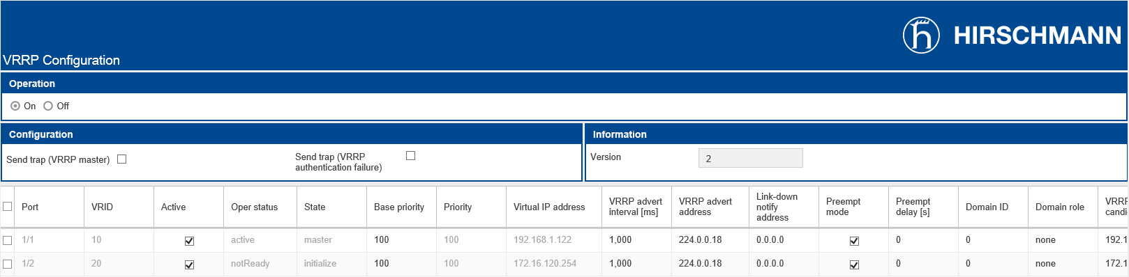
On Router # 2’s Routing - L3-Redundancy - VRRP - Configuration page of the GUI, click the Reload button ( ). Notice that port 1/2 is in the Master state.
On Router # 1, reconnect the cable on Port 1/2, and then click the Reload button ( ). Notice that Port 1/2 is back in the “ master “ state, and the Oper status is “ active “.
On Router # 2, click the Reload button ( ). Notice that Port 1/2 is back in the “ backup “ state.
You can perform the same tests for Port 1/1 on Router # 1, but you will want to access both switch’s GUI from the 172.16.120.0 side of the network. Otherwise, when you disconnect the cable on port 1/1 of Router # 1, you will lose connection to the router.
These routers can now provide router redundancy for the 192.168.1.0/24 and 172.16.120.0/24 networks using the Virtual Router Redundancy Protocol (VRRP) in the event of a single complete router failure.
NOTE: It is highly advisable to configure some appropriate tracking options for these redundant routers so that if only a single router interface fails, and not the entire router, routing can still function between these two networks without human intervention.
Additional Information
Command Line Interface (CLI) Commands:
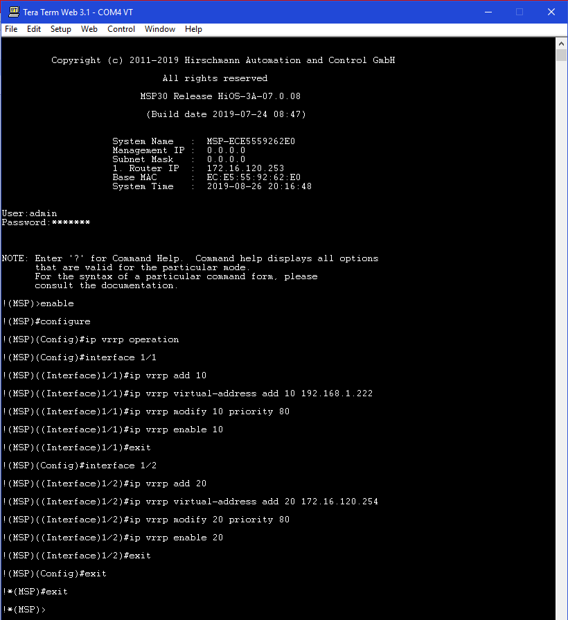
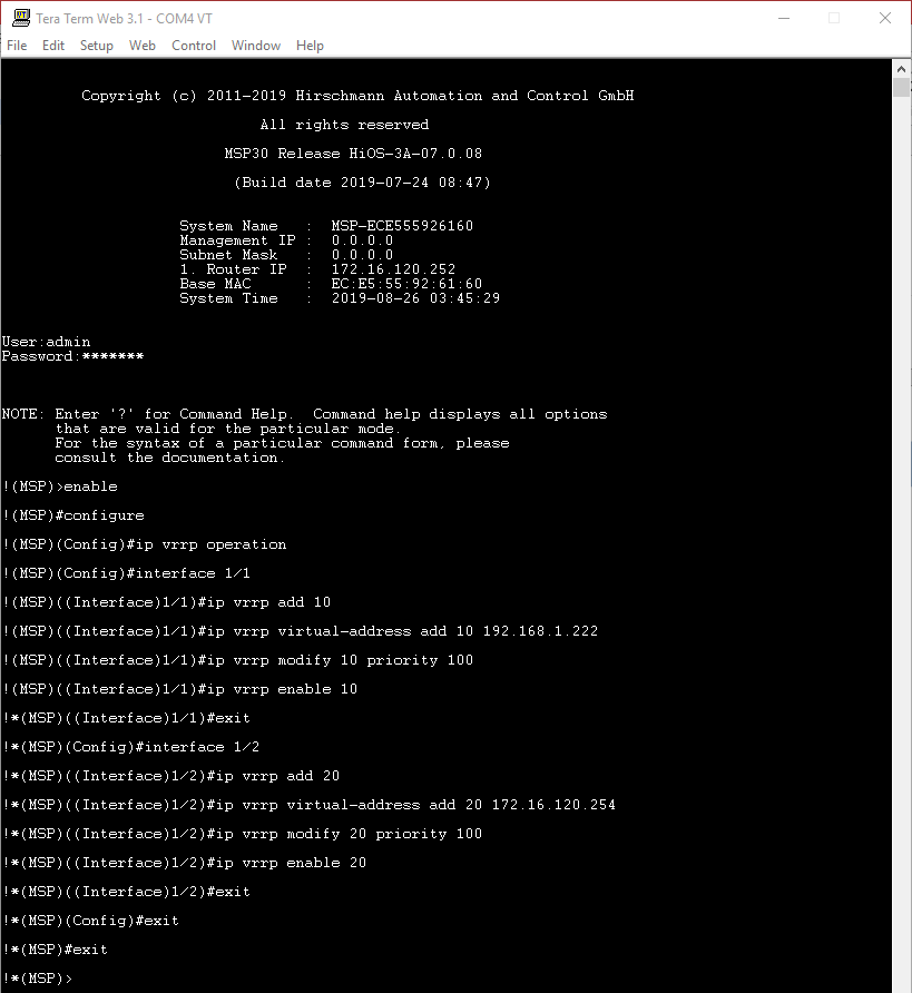
The following CLI commands can be used in lieu of the HTMLv5 GUI to configure the Virtual Router Redundancy settings to meet the same configuration requirements.
On Router # 1:
On Router # 2: