This article describes the basic steps required to configure VLAN-Based (Virtual ) Router Interfaces on Hirschmann Platform V Layer 3 switches running the HiOS firmware version 07.0.00 or higher and the new HTMLv5 Graphical User Interface (GUI).
HiOS-3S or 3A & Firmware 07.0.00
With the introduction of the HiOS firmware version 07.0.00, the switch agent’s Graphical User Interface (GUI) has been changed from a Java based interface to a HTML v5 interface.
Configuration Tasks:
The configuration of the routing function usually contains the following steps:
- Draw a Network Plan
Create a picture of your network so that you can clearly see the division into subnetworks and the related distribution of the IP addresses.
This step is very important. Good planning of the subnetworks with the corresponding network masks makes the router configuration much easier.
2. Router Basic Settings
Along with enabling the global routing function, the router basic settings also contain the assignment of IP addresses and network masks to the router interfaces, and then enabling the routing function on that specific interface.
VLAN-Based (Virtual) Router Interfaces:
A VLAN-based router interface is one or more physical ports that are combined using VLANs to build a virtual router interface.
If there are no active ports that are a part of the VLAN-based router interface, then the entry from the routing table is removed, because the router transmits exclusively to those ports for which the data transfer is likely to be successful. The entry in the interface configuration table remains.
Between devices attached to the same VLAN of the VLAN-based router interface, the switch exchanges data packets on Layer 2.
Terminal devices address data packets with a destination address in another subnet to the router. The device then exchanges the data packets on Layer 3.
Note:
When you assign the VLAN ID of the management VLAN to a router interface, the device deactivates the management IP address. You can then access the device via the IP address of the router interface. The management VLAN is the VLAN by means of which you access the management of all the devices.
The Network Design:
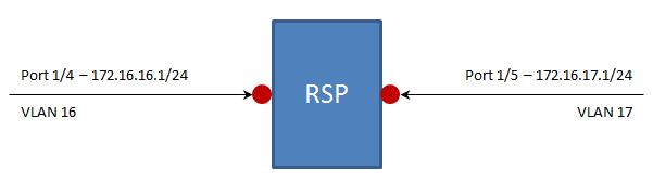
In this article, we will use a RSP switch with Layer 3 Standard features to configure two VLAN-Based (Physical) Router Interfaces.
We will configure interface Port 1/4 and Port 1/5 as VLAN-Based (Virtual) Router interfaces using IP Address in separate subnets.
The Configuration Steps:
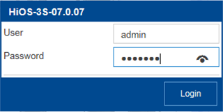
Log into the switch’s GUI with a user ID that has administrative privileges. In the switch’s default configuration, this would be accomplished using the User ID of “ admin “ and a password of “ public “.
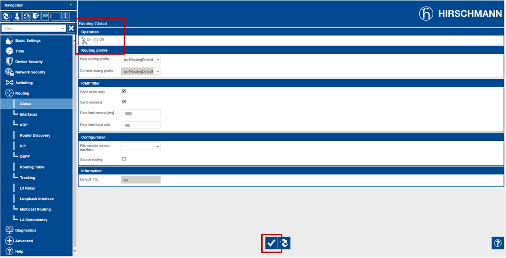
Navigate to the Routing – Global page of the GUI.
Enable the Routing Global operation by selecting the On Operation option radial button and then click the Set button ( ).
).
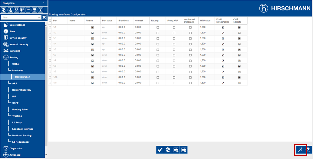
Navigate to the Routing – Interfaces – Configuration page of the GUI.
Click the Wizard button ( ).
).
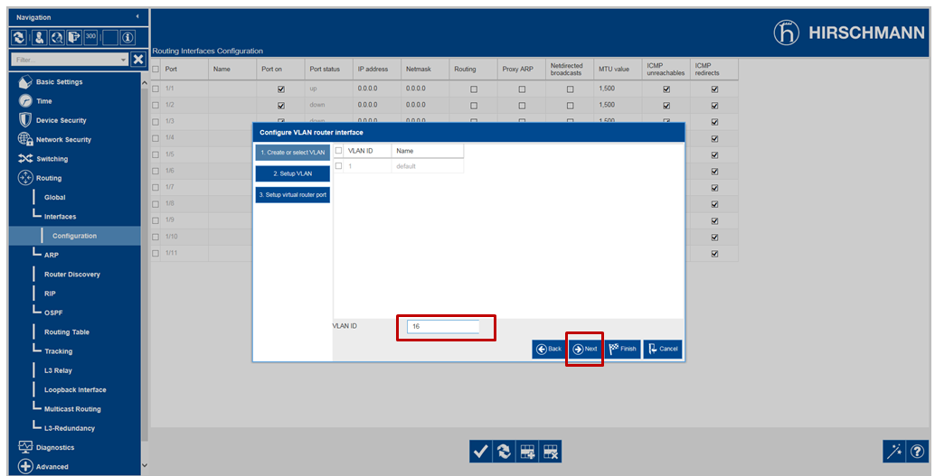
Enter 16 in the VLAN ID field and click the Next button ( ).
).
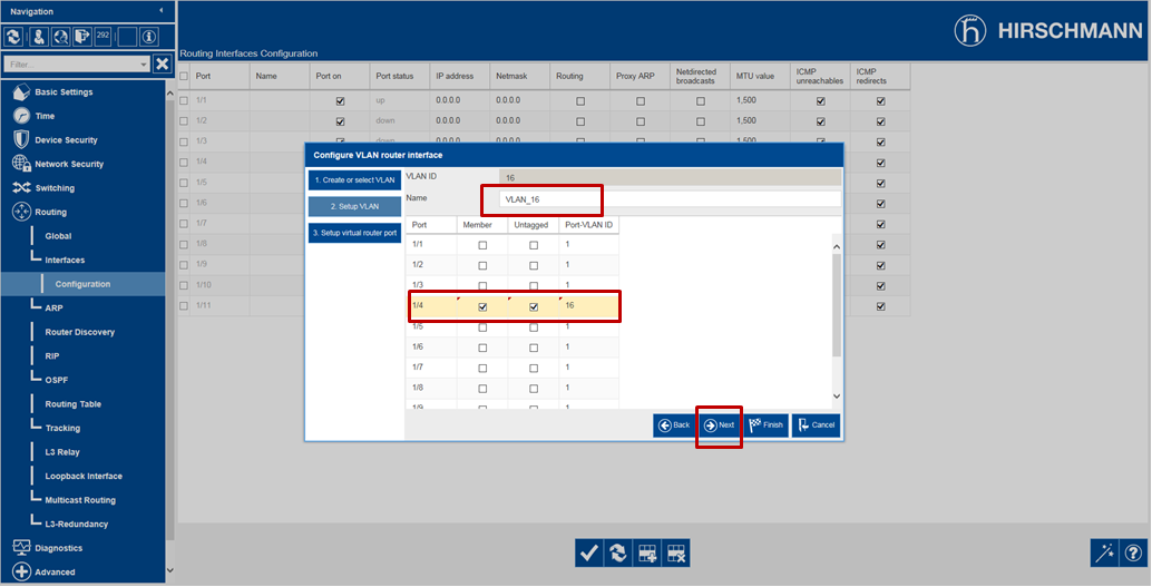
Select the Member and Untagged checkboxes for Port 1/4.
Enter 16 for the Port-VLAN ID field for Port 1/4 and click the Next button ( ).
).
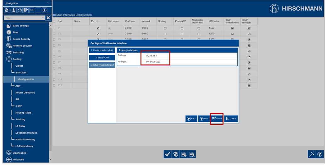
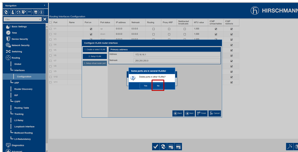
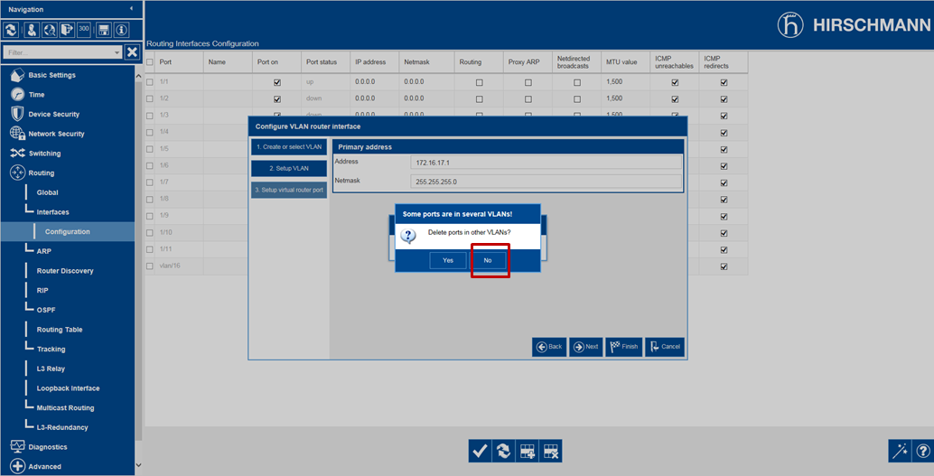
Enter 172.16.16.1 for the Primary Address and 255.255.255.0 for the Netmask, and then click the Finish button ( ).
).
Click No when asked to “Delete ports in other VLANs”.
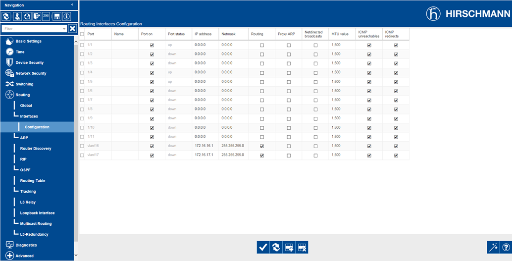
The newly created VLAN-Based Router Interface will appear in the Routing – Interfaces – Configuration page of the GUI as Port vlan/16.
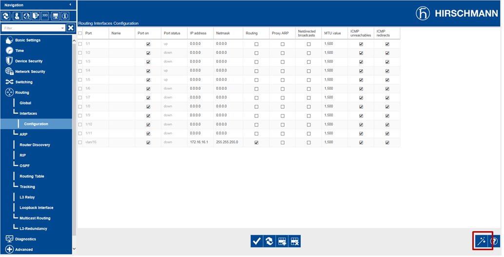
Click the Wizard button ( ) again.
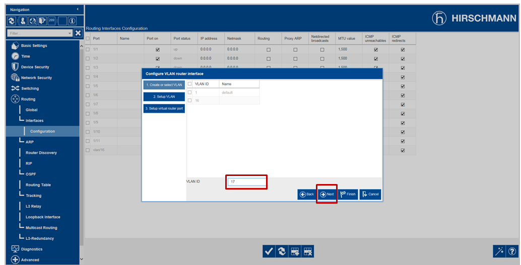
Enter 17 in the VLAN ID field and click the Next button ( ).
).
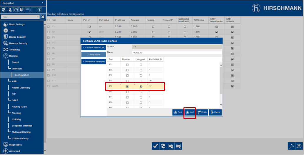
Select the Member and Untagged checkboxes for Port 1/5.
Enter 17 for the Port-VLAN ID field for Port 1/5 and click the Next button ( ).
).
Enter 172.16.17.1 for the Primary Address and 255.255.255.0 for the Netmask, and then click the Finish button ( ).
).

Click No when asked to “Delete ports in other VLANs”.
The newly created VLAN-Based Router Interface will appear in the Routing – Interfaces – Configuration page of the GUI as Port vlan/17.
This completes the steps required to configure VLAN-Based (Virtual) Router Interfaces for Ports 1/4 and 1/5.
Verifying the Configuration:
Once we have completed the steps required to configure Ports 1/4 an 1/5 as VLAN-Based (Virtual) Router Interfaces, we should ensure that the ports are now capable of routing IP Packets.
Remember, if at least one of the ports that are configured as a member of the VLAN-Based (Virtual) Router Interface does not have an active Ethernet connection, it can/will not be able to do any routing. So, make sure that you have at least one active Ethernet connection for the ports associated with VLAN/16 and VLAN/17.
Navigate to the Routing – Routing Table page of the GUI.
Click the Reload button ( ).
).
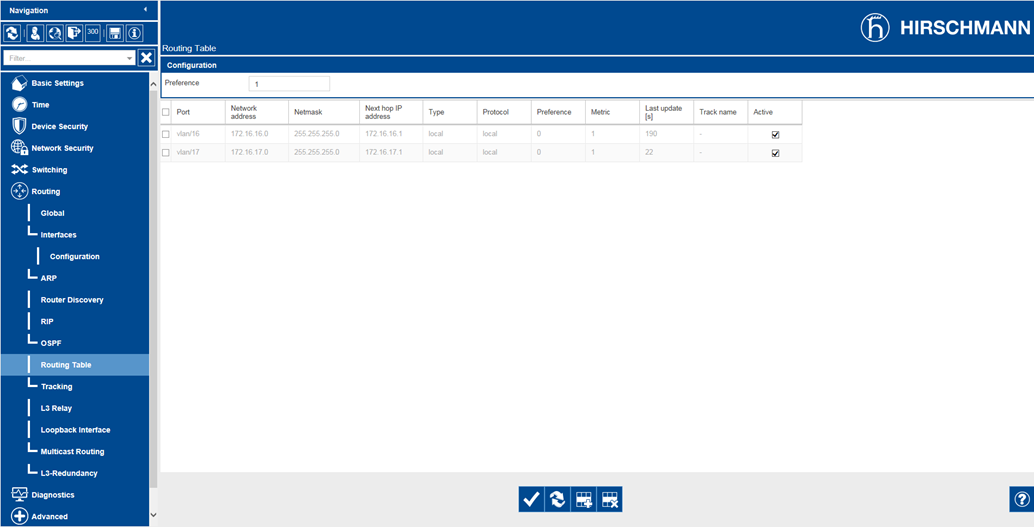
You should see the two ports listed as having active routes to the IP 172.16.16.0 and 172.16.17.0 networks. Because they are router interfaces configured on this switch, they will be listed as a Local Type.
This switch can now route IP Packets between the two IP networks.
Additional Information
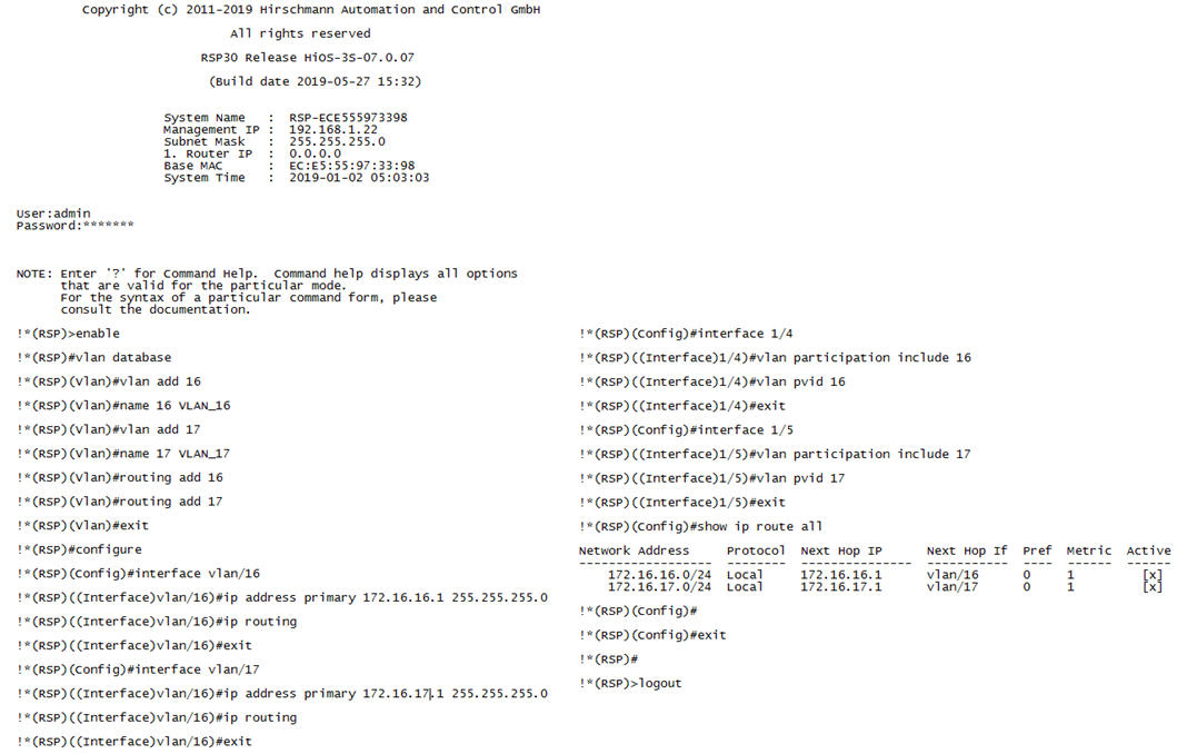
Command Line Interface (CLI) Commands:
The following CLI commands can be used in lieu of the HTMLv5 GUI to configure the switch for Port-Based (Physical) Router Interfaces to meet the same configuration requirements.