


This guide is designed to assist in the importing and the configuration of the AOI for HiOS switches in Studio 5000.
Switch Configuration and EDS file
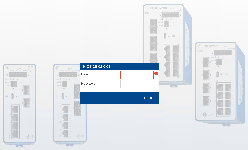
- Login to the switch
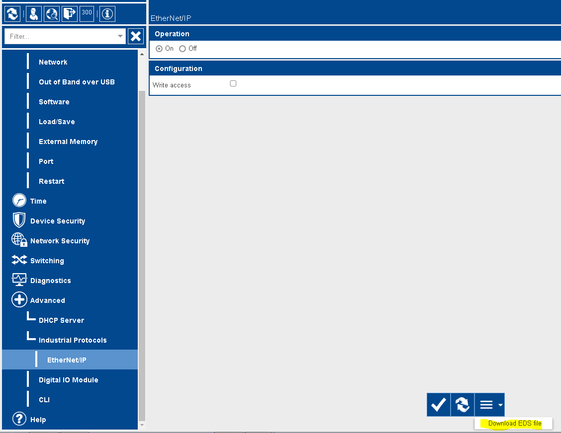
2. Go to the “Advanced” menu, turn on ENIP operation, click the check mark to write the change. Click on the hamburger button at the bottom of the page and click to download the EDS file. This will need to be done for the different models of switches being monitored.
Rockwell Software configuration
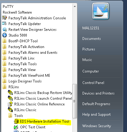
- Use the RSlinx EDS hardware Installation tool and add the EDS file downloaded from the switch(es).
Note: If needed there is a how to guide to assist with adding the EDS file
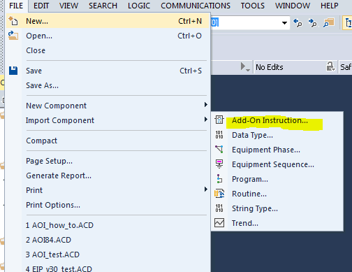
2. In the Studio 5000 PLC program, go to “File”, “Import Component”, and “Add-on Instruction”
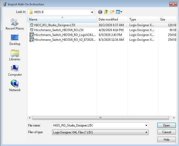
3. Browse to the AOI file (see related content), click to highlight it and click the “Open” button
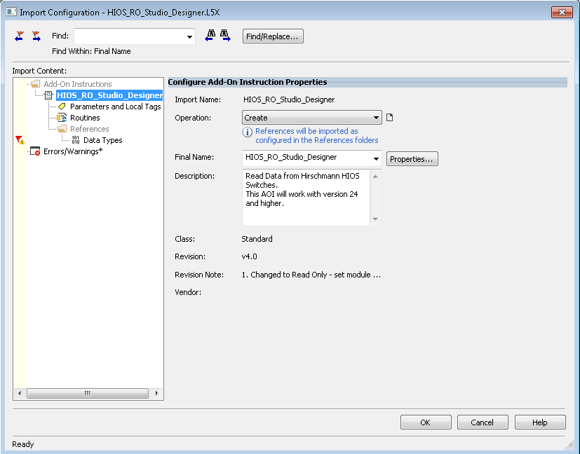
4. Click OK
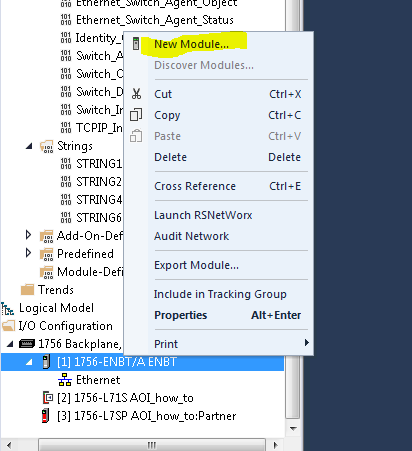
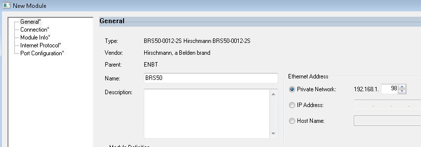
5. Right-click on the comm module and select “New Module”
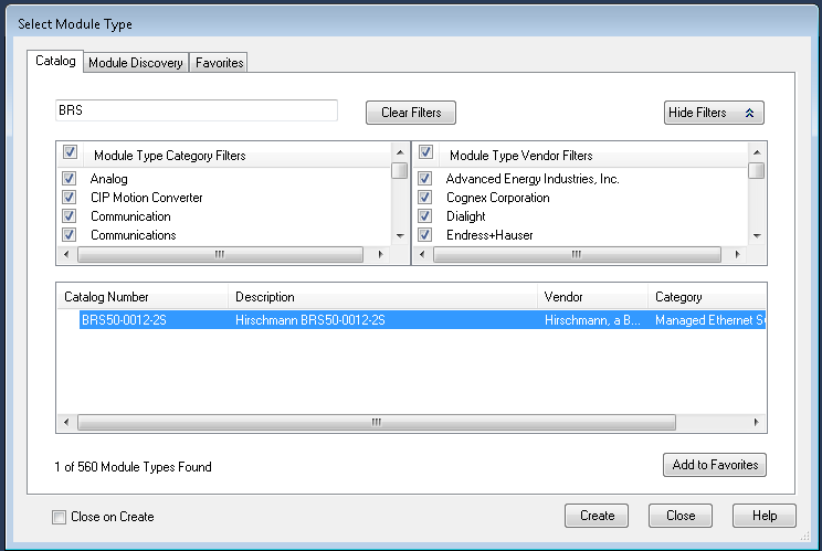
6. Find the Switch that needs to be monitored and click “Create”
7. Name the module and assign an IP address
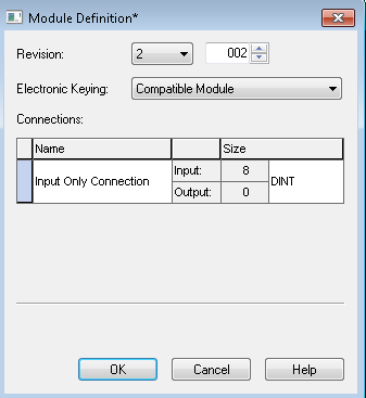
8. Click the change button, change to “Input only” and “DINT”, click OK, and OK again
9. Open the main routine, go to “Add-On” and click on the “HIOS RO add-on”
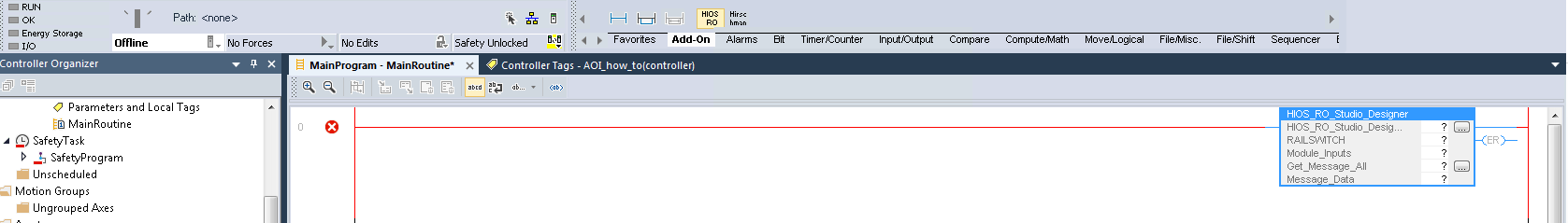
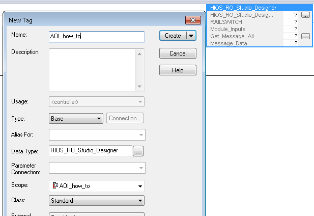
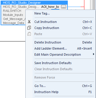
10. Right-click on the “HIOS_RO_Studio_Designer”, and select “New tag”
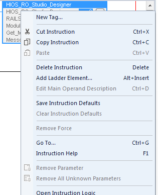
11. Name the tag and click “Create”
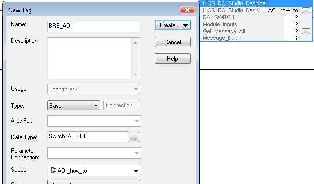
12. Right-click on the Railswitch and select “New tag”
13. Name the tag and click “create”
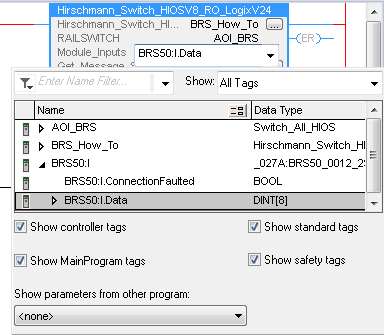
14. For the Module_inputs select the I.Data from the switch created in previous step
15. Right-click on the “Get Message All ?” and select “New tag”
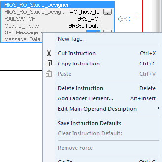
16. Name the tag and click “Create”
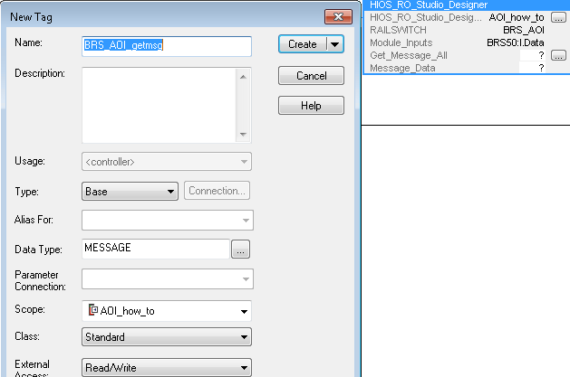
“
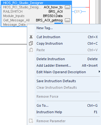
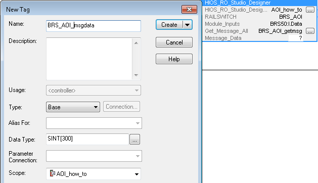
17. Right-click on the Message_data ?” and select “New tag”
18. Name and click “Create”
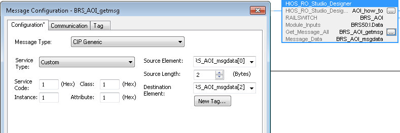
19. Click on the “Get_Message_all” config box and set the service code, class, Instance, and attribute to 1. Also set the Source element to the “msgdata[0] tag” created in a previous step. The “source length” is set to 2 and the “Destination element” is the msgdata[2]
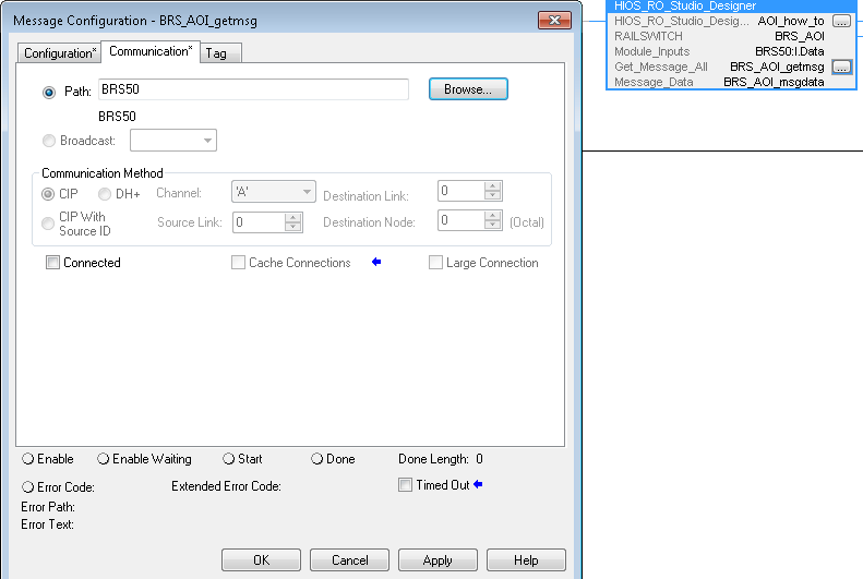
20. Go to the “Communications” tab, set the path to the switch and click OK
21. Make sure the tags are populated and the configuration is now complete.