How to Configure Tracking on Hirschmann Layer 3 Switches with HiOS-3S & 3A and Firmware Version 07.0.00 or Higher, with VRRP Redundancy already configured.
This article describes the basic steps required to configure Tracking options for use in conjunction with the Virtual Router Redundancy Protocol (VRRP ) on Hirschmann Platform V Layer 3 switches running the HiOS firmware version 07.0.00 or higher and the new HTMLv5 Graphical User Interface (GUI).
HiOS-3S or 3A & Firmware 07.0.00
With the introduction of the HiOS firmware version 07.0.00, the switch agent’s Graphical User Interface (GUI) has been changed from a Java based interface to a HTML v5 interface.
Configuration Tasks:
The configuration of the routing function usually contains the following steps:
1. Draw a Network Plan
Create a picture of your network so that you can clearly see the division into subnetworks and the related distribution of the IP addresses.
This step is very important. Good planning of the subnetworks with the corresponding network masks makes the router configuration much easier.
2. Router Basic Settings
Along with enabling the global routing function, the router basic settings also contain the assignment of IP addresses and network masks to the router interfaces, and then enabling the routing function on that specific interface.
3. Configure VRRP settings
In another article, I covered the steps required to configure the VRRP routing functionality that will be used as the base configuration for this the concepts and steps illustrated in this article. Please see the document titled “How to Configure VRRP on Hirschmann Layer 3 Switches with HiOS “.
4. Configure Tracking Objects
- Interface Objects
- Ping Objects
- Logical Objects
5. Assign the tracking Object to an Application
- Assign Tracking Object to Static Route Entries
- Assign Tracking Objects to VRRP Router Configurations
Tracking
The tracking function allows you to monitor what are known as tracking objects. Examples of monitored tracking objects are the link statuses of an interface or the reachability of a remote router or end device, or a logical combination of both the interface and/or ping tracking objects.
The device forwards status changes of the tracking objects to the registered applications, for example, to the routing table or to a VRRP instance.
The applications then react to the status changes:
In the routing table the device activates/deactivates the route linked to the tracking object based upon the object's current status.
The VRRP instance linked to the tracking objects reduces the priority of the virtual router so that a backup router can assume the role of the master VRRP router.
This article will focus on the theory and tasks surround the configuration of tracking objects for use in conjunction with VRRP.
The Theories
How VRRP Works
VRRP is a type of “gateway redundancy”. VRRP describes a process that groups multiple routers into 1 virtual router. End devices always address the virtual router, and VRRP helps to ensure that a physical router belonging to the virtual router takes over the data transmission. Even if a physical router fails, VRRP helps to ensure that another physical router takes over the distribution tasks as part of the virtual router.
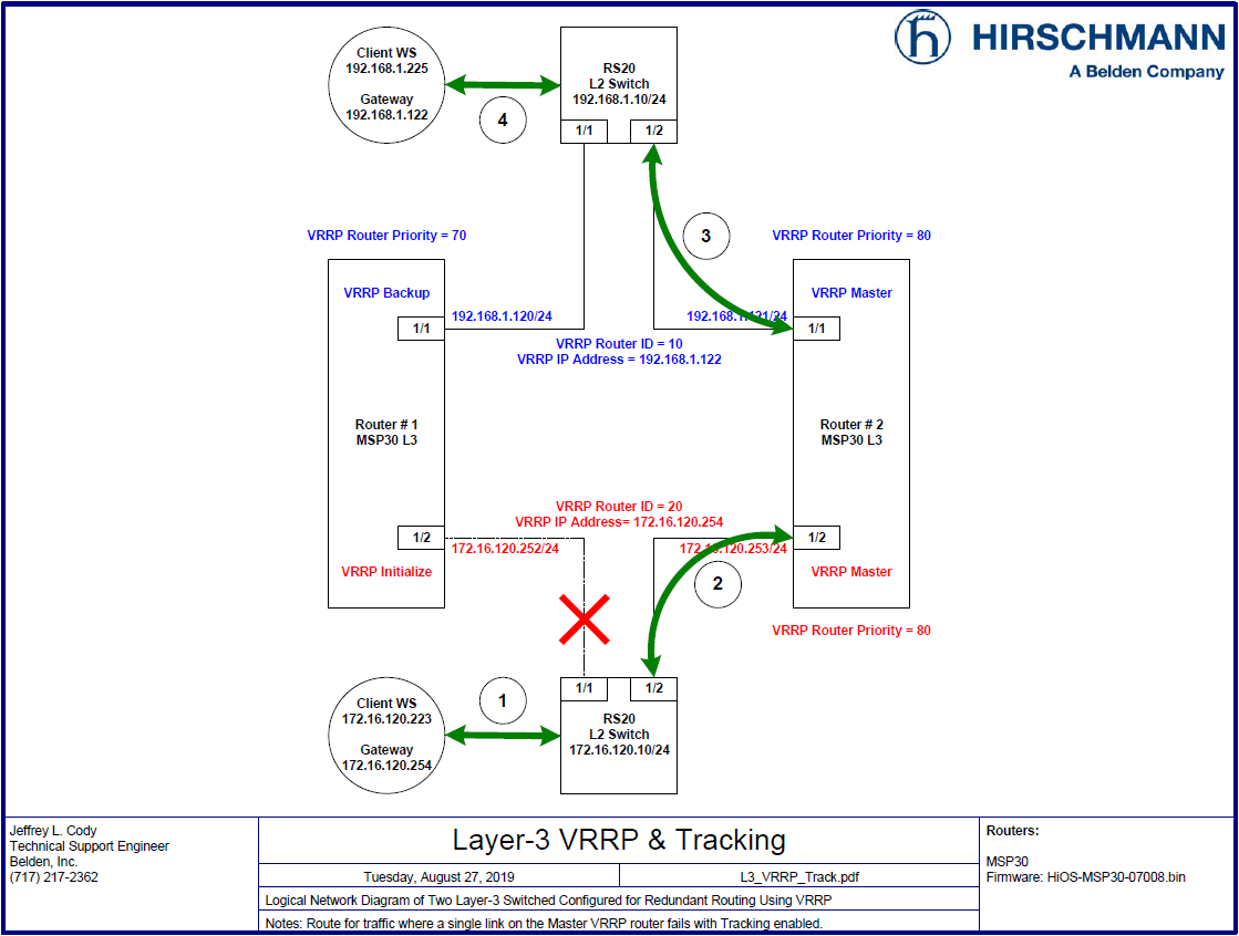
Consider the following diagram:
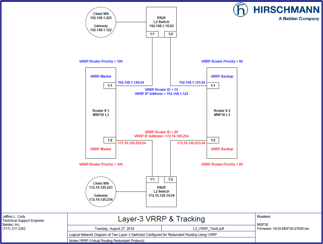
In the diagram above, we see a common VRRP configuration between two routers, Router # 1 and Router #2.
The two routers exchange VRRP information on each network using the VRRP protocol. Part of that information details which virtual router ID is being advertised for a given network as well as the VRRP priority of each router for that virtual router. The router with the highest VRRP priority for a given virtual router becomes the master. The other router becomes the backup. The master assumes the role of the VRRP interface, which the clients use as their default gateways, and routes the traffic according to it’s routing tables. If the master VRRP router fails to send out normal VRRP advertisements within a given timeframe, the backup VRRP router assumes the master has failed and takes over the role of the master VRRP router. There is no need to reconfigure the gateways on the clients when this change takes place.
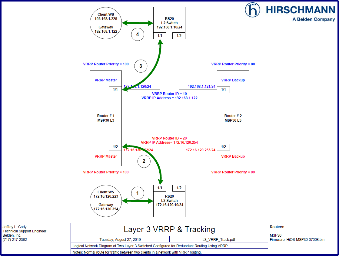
This drawing shown the normal traffic route that is used when the Client WS in the 172 network pings the Client WS in the 192 network when Router # 1 is functioning as the VRRP master router.
- The Client sends a ping packet to its default gateway, 172.16.120.254, via the L2 switch.
- The L2 switch forwards the ping packet to Router # 1, port 1/2, because the master VRRP router is answering ARP replies for the IP Address 172.16.120.254, which is defined as the Client WS’s default gateway. Router # 1 is functioning as the master VRRP router for the VRRP Router ID 20 because it has a higher priority (100) than the backup VRRP Router # 2, which has a lower VRRP Priority (80).
- Router # 1 forwards the packet to the L2 switch on the upper network based upon its routing table.
- The L2 switch forwards the ping packet to the Client WS. The Client WS in the 192 network sends a ping reply back to the Client WS in the 172 network via Its defined default gateway, which is also Router # 1 for the VRRP router 10, following the same path back to the Client WS in the 172 network.
So long as the VRRP master’s links remain up, and it can route traffic to each network, and it remains the router with the highest VRRP priority for each VRRP router ID, the traffic will continue to use these paths for communication traffic between the two Client Ws’.
The Issue with VRRP
Consider the following diagram:
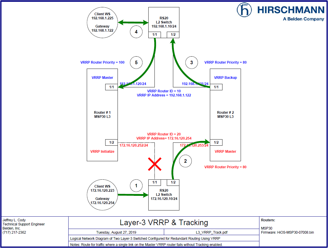
In the diagram above, if we have a failure of the link between Router # 1 and the L2 switch in the 172 network, without Tracking configured, we can have a scenario routing between the two Client WS’ will fail.
- The Client sends a ping packet to its default gateway, 172.16.120.254, via the L2 switch.
- The L2 switch forwards the ping packet to Router # 2, port 1/2, because it is the master VRRP router and is answering ARP replies for the IP Address 172.16.120.254, which is defined as the Client WS’s default gateway. Router # 2 is functioning as the master VRRP router for the VRRP Router ID 20 because it is not receiving any other VRRP advertisements for the VRRP router ID 20.
- Router # 2 forwards the packet to the L2 switch on the upper network based upon its routing table.
- The L2 switch forwards the ping packet to the Client WS.
- The Client WS in the 192 network sends a ping reply back to the Client WS in the 172 network via Its defined default gateway, which is still Router # 1 for the VRRP router 10, but since Router # 1 now does not have a known route to the 172 network down below, it will drop the packet, and the communications will fail.
The Tracking Solution
Consider the following diagram:
In the diagram above, if we have the same failure of the link between Router # 1 and the L2 switch in the 172 network, and Interface and Ping Tracking is properly configured, we can overcome the previous failure scenario by demoting the VRRP priority on Router # 1 if it senses a failure of the link on port 1/2 by lowering the VRRP priority to 70 for the VRRP router ID 10 on the 192 network.
The result is that Router # 2 would become the master VRRP router for both VRRP router IDs 10 & 20, because for each virtual router, it has the highest known VRRP priority, and Router # 1 would become the backup VRRP router for VRRP router ID 10.
The advantage is that no manual actions were needed either on the clients or the routers. Once the issue with the link is resolved, Router # 1 would once more become the master for both VRRP router IDs, and Router # 2 would reassume the backup roles.
The Configuration Steps:
Log into the Router # 1’s GUI with a user ID that has administrative privileges. In the switch’s default configuration, this would be accomplished using the User ID of “ admin “ and a password of “ public “.
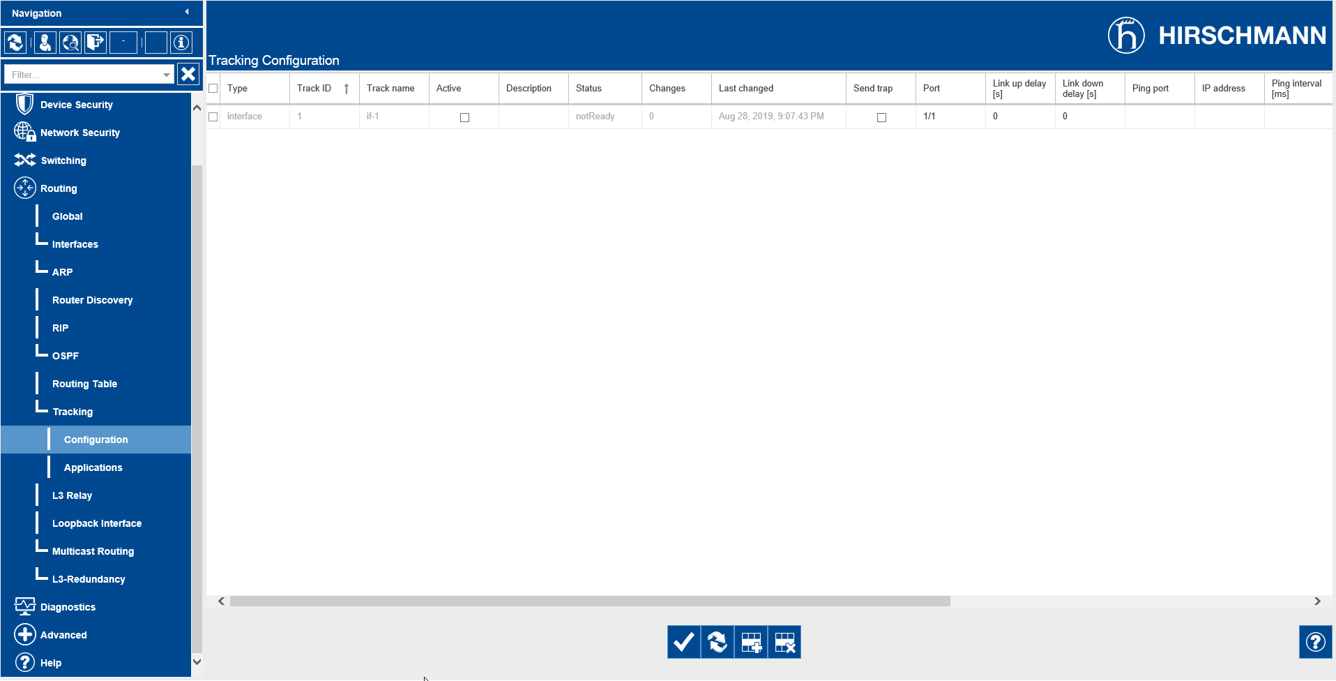
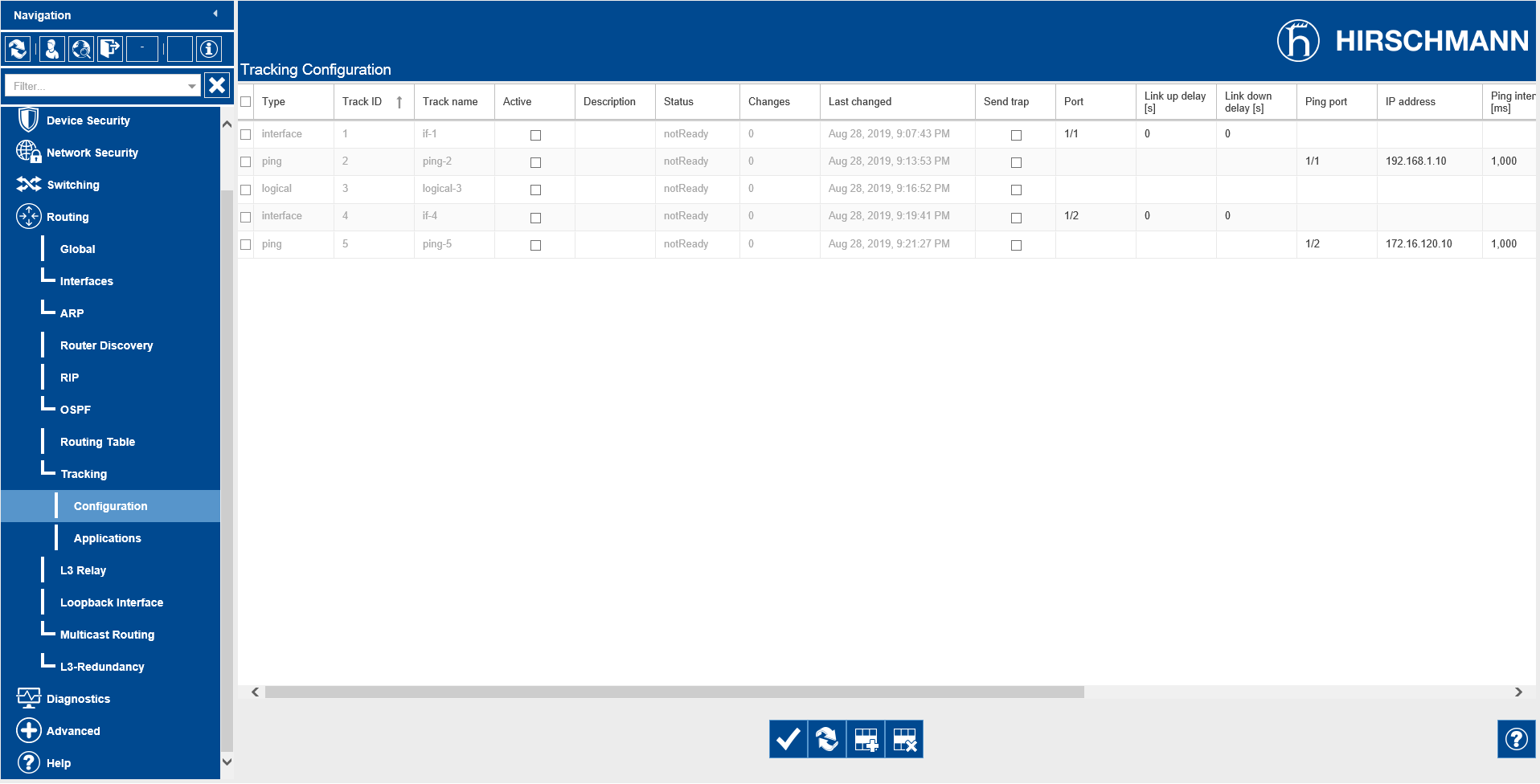
Navigate to the Routing – Tracking - Configuration page of the GUI.
Click the Create entry button ( ) at the bottom of the page.
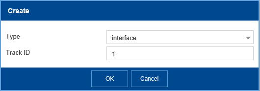
Select interface for the Type and enter “ 1 “ for the Track ID, then click OK.
Select Port 1/1 in the Port column, then click the Write ( ) button at the bottom of the page.
Click the Create entry button ( ) at the bottom of the page.
Select ping for the Type and enter “ 2 “ for the Track ID, then click OK.

Select Port 1/1 for the Ping Port and enter “ 192.168.1.10 “ for the Ping Address, then click the Write ( ) button at the bottom of the page.

Click the Create entry button ( ) at the bottom of the page.
Select logical for the Type and enter “ 3 “ for the Track ID, then click OK.
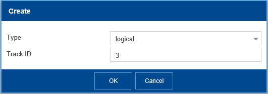
Select if-1 for Logical operand A and ping-2 for Logical operand B and “ and “ for the operator, then click the Write ( ) button at the bottom of the page.
Click the Create entry button ( ) at the bottom of the page.
Select interface for the Type and enter “ 4 “ for the Track ID, then click OK.
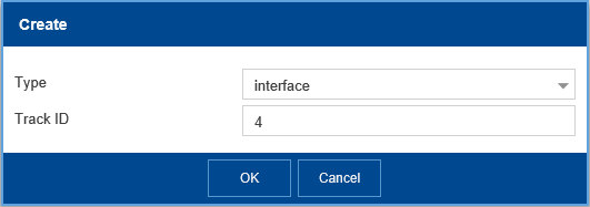
Select Port 1/2 in the Port column, then click the Write ( ) button at the bottom of the page.
Click the Create entry button ( ) at the bottom of the page.
Select ping for the Type and enter “ 5 “ for the Track ID, then click OK.
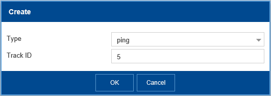
Select Port 1/2 for the Ping Port and enter “ 172.16.120.10 “ for the Ping Address, then click the Write ( ) button at the bottom of the page.
Click the Create entry button ( ) at the bottom of the page.
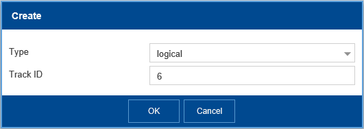
Select logical for the Type and enter “ 6 “ for the Track ID, then click OK.
Select if-4 for Logical operand A and ping-5 for Logical operand B and “ and “ for the operator, then click the Write ( ) button at the bottom of the page.
Click the Create entry button ( ) at the bottom of the page.
Select logical for the Type and enter “ 7 “ for the Track ID, then click OK.

Select logical-3 for Logical operand A and logical-6 for Logical operand B and “ and “ for the operator, then click the Write ( ) button at the bottom of the page.
Make all of the entries Active, then click the Write ( ) button at the bottom of the page.

Navigate to the Routing – Layer3-Redundancy-VRRP-Configuration page of the GUI.
Click the Wizard button ( ) at the bottom of the page.
Select Port 1/1 for the Port entry and then click the Next button ( ) at the bottom of the page.
Click the Next button ( ) at the bottom of the page, again.
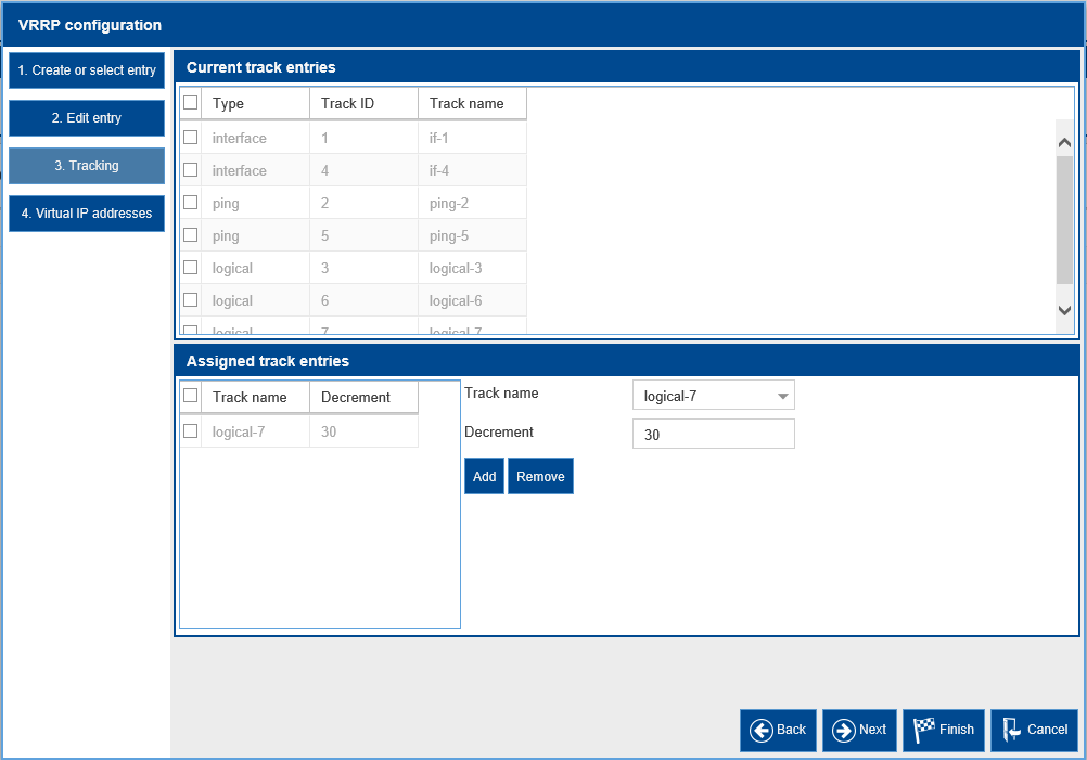
Select logical-7 for the Track name and enter “ 30 “ for the Decrement, then click the add button.
Click the Next button ( ) and then the Finish button (
 ) at the bottom of the page.
Click the Wizard button ( ) at the bottom of the page.
Select Port 1/2 for the Port entry and then click the Next button ( ) at the bottom of the page.
Click the Next button ( ) at the bottom of the page, again.
Select logical-7 for the Track name and enter “ 30 “ for the Decrement, then click the add button.

Click the Next button ( ) and then the Finish button (
 ) at the bottom of the page.
Navigate to the Routing – Tracking - Applications page of the GUI.
Verify that for the applications VRRP 1/1 VRID: 10 & VRRP 1/2 VRID: 20, both have logical-7 defined as the Track Name.
Repeat all of the configuration steps above for Router # 2.
Verifying the Configuration:
Once we have completed the steps required to configure the Tracking options for Router # 1 and Router # 2, we should ensure that VRRP Protocol and the Tracking options functions properly in the event of a failure.
On both routers, Navigate to the Routing – Layer3-Redundancy-VRRP-Configuration page of the GUI.
On Router # 1, disconnect the link connected to Port 1/2.
Click the Reload button ( ) on both Routers.
Notice that on Router # 1, the Port 1/1 is in a Backup state and Port 1/2 is in a notReady state.
Also notice that their current priority is “ 70 “, with is 30 less than the configured priority.
Notice that on Router # 2, both ports are in the Master state.
On Router # 1, reconnect the link connected to Port 1/2.
Click the Reload button ( ) on both Routers.
Router # 1 should again be the Master for both VRRP instances and Router # 2 should be Backup for both VRRP instances.
Additional Information
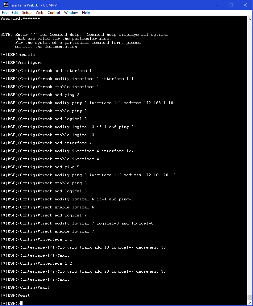
Command Line Interface (CLI) Commands:
The following CLI commands can be used on both routers in lieu of the HTMLv5 GUI to configure the Tracking option settings to meet the same configuration requirements.