Configuring PTP in Hirschmann Switches for use with Kinetix 5700 Drives
PTP (Precision Time Protocol) is a procedure described in the IEEE 1588-2008 standard that enables the clocks in the network to be synchronized to a degree of precision of just a few 100 ns. Kinetix5700 drives must be time synchronized with the PLC to ensure commanded position and velocity matches actual position and velocity at a given time. PTP (also called CIP sync) communication is used to do achieve this time synchronization.
This guide is for Hirschmann switches using the HiOS platform such as the OS20/30, RPS, RPSE, etc.
Switches using the Classic OS platform are mostly limited to PTP simple mode which allows the switch to set its internal time using PTP traffic from a master close (such as a PLC), however the switch is unable to forward PTP traffic making it impossible to establish a synchronization between the PLC and Kinetix5700. This applies to RS20/30 switches
PTP Configuration in Hirschmann Switch
This guide will provide the steps to configure 2 ports to be PTP enabled. As a prerequisite this guide will assume the switch has been configured with an IP address and the user has HiView.
Also note that PTP requires all devices to be communicating in full duplex. This can achieved by ensuring that all devices and switch ports are set to auto negotiate or by individually setting all devices and switch ports to full duplex manually. If there is a duplex mismatch, for example the switch port is set to auto negotiate and the Kinetix drive is set to 100/Full, the switch will default to half duplex which will prevent PTP synchronization.
Step 1: Connect to the switch on Port 3 and open the web interface using HiView.
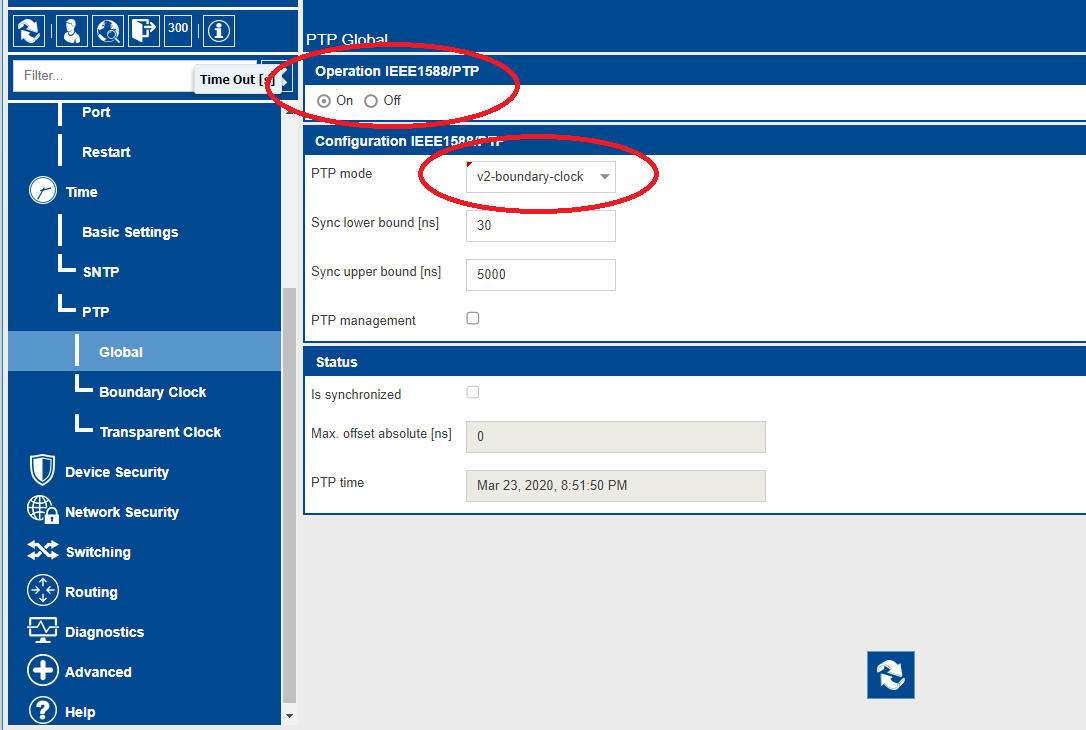
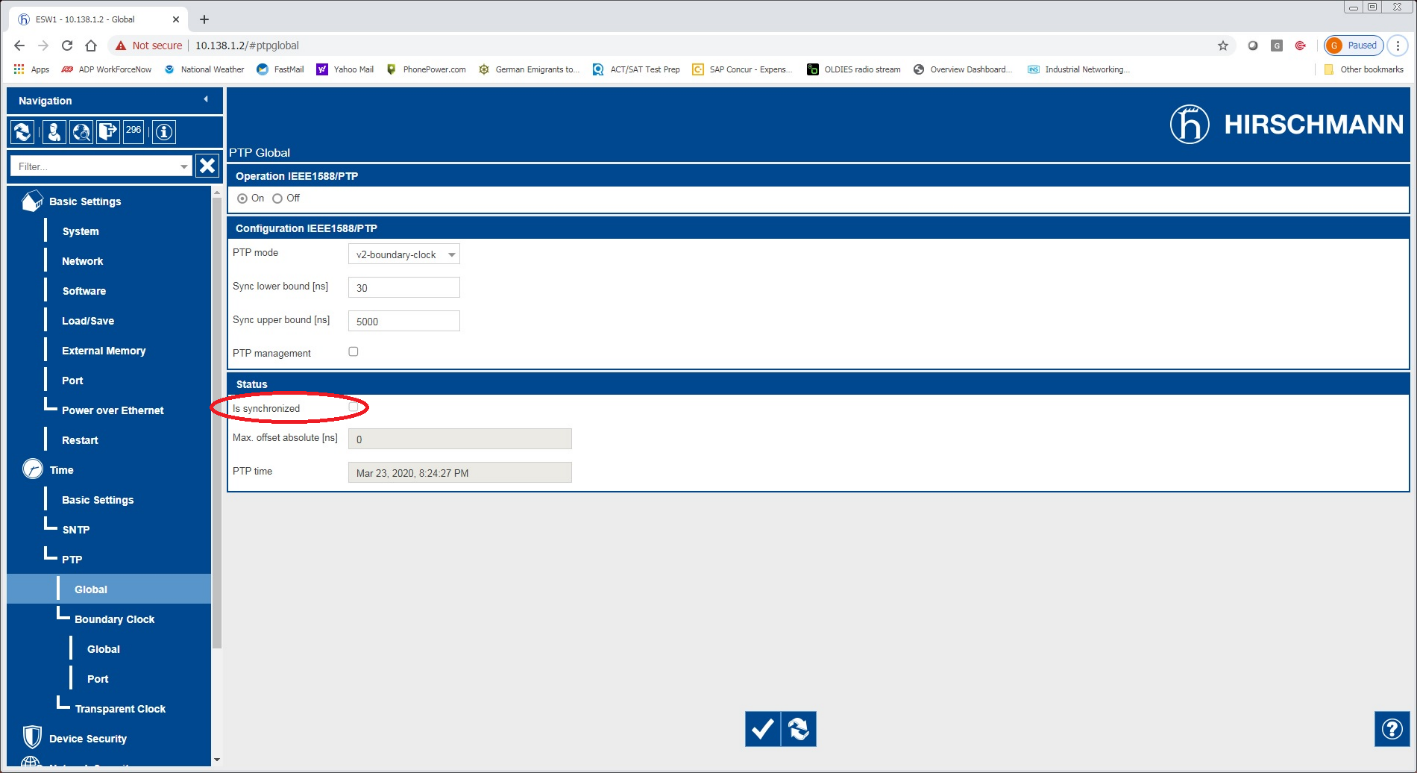
Step 2: Browse the main menu to Time -> PTP -> Global. Set Operation IEEE 1588/PTP to On and set PTP mode to v2-boundary-clock. When complete press the write button at the bottom of the page.
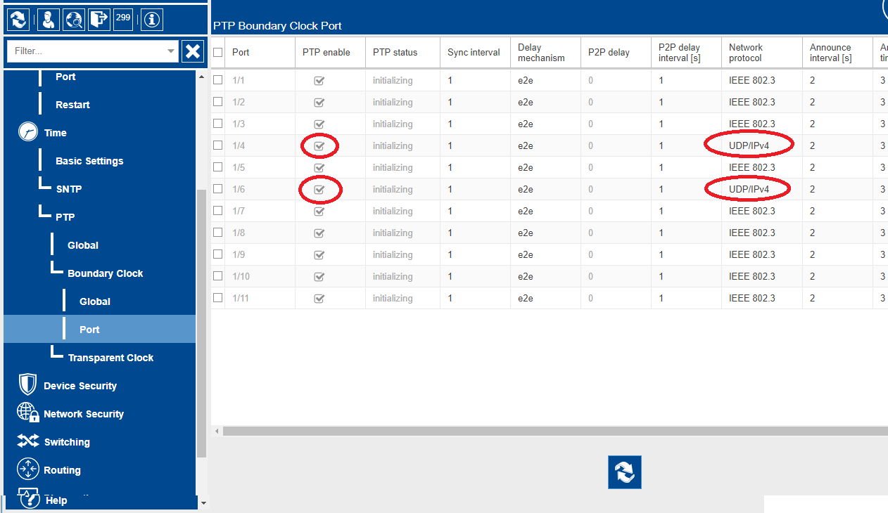
Step 3: Configure PTP port settings. Select the checkbox for PTP enable for each port that requires PTP – this includes the PLC and all Kinetix5700 drives. In the event that the PLC and Kinetix5700 drives are connected to different switches, the ports connecting the switches to each other must also be enabled. The network protocol for all enabled ports needs to be set to UDP/IPv4.
PLC Configuration
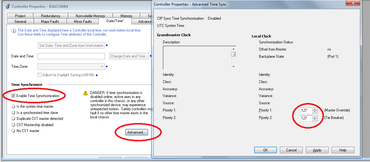
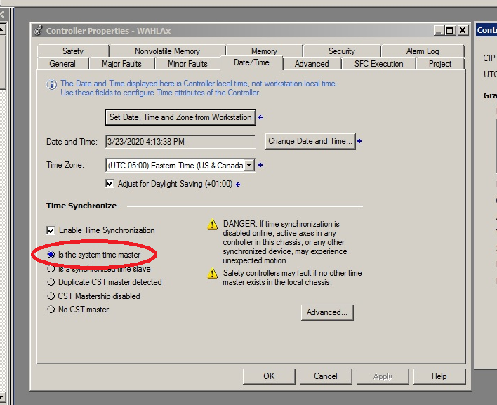
Step 1: Go to Controller Properties -> Date/Time. Select the “Enable Time Synchronization” check box to enable PTP. Then go advanced options and change the Priority 1 and Priority 2 values to 127. Changing the priority value will ensure that the PLC is the time master
Time Synchronization Verification
In the PLC controller properties verify that the PLC is the system time master
Connect to the switch and browse to Time->PTP->Global. Verify that the status “Is Synchronized” is active.
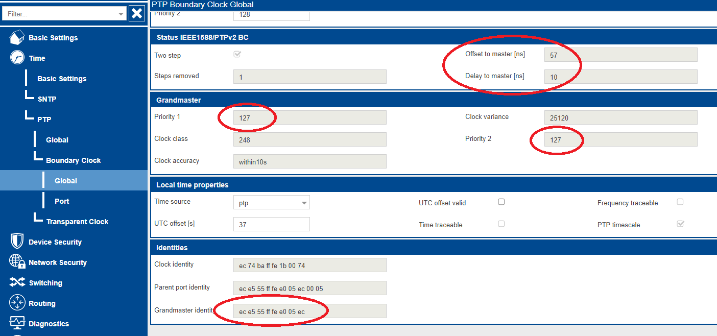
Next browse to Time->PTP->Boundary Clock->Global. Here you should be able to see the Priority 1 and 2 values under Grandmaster match the 127 set in the PLC Date/Time settings. The Grandmaster Identity should be the MAC address of the PLC EN2T card with “ff fe” added between bytes 3 and 4. Also, you should be able to see the Offset to master and Delay to master values – these will update each time the page is refreshed.
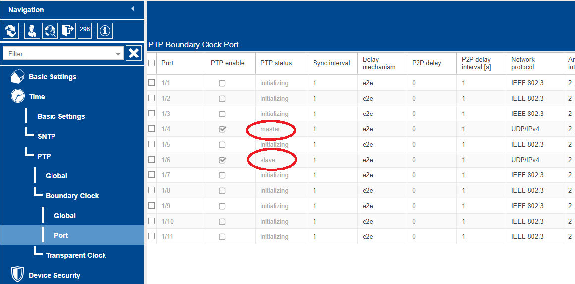
Finally browse to Time->PTP->Boundary Clock->Port. This screenshot shows an install where the PLC is connected to port 6 and the drive(s) are connected to port 4. The PTP status for the PLC port will be shown as “slave” as the switch is a PTP slave to the PLC. The drive(s) will be shown as “master” as the switch relays the PTP traffic from the PLC, becoming the master to the drive(s).